|

| |  |

|

slingsteel
New User
Jul 5, 2014, 9:54 AM
Post #1 of 10
(7196 views)
|
I have a 1997 GMC 1500 4x4 5.7L automatic 230k miles.
I have own this truck since 2000, the only major problems since then I have had to replace the fuel pump two times about 90K miles on each one.
Update the spider at around 180k (delphi unit)
A set of heads around 195K both were cracked.
All work performed by me.
About a month ago my daughter called and said the truck died, luckily only a couple of hundred feet from home.
No CEL on.
Naturally first thing comes to mind a bad fuel pump.
Tested it and it reads 60psi with key turn on. So I checked for spark, none at plugs, coil had spark.
So I remove ICM and go to Autozone to have it tested. Tests bad buy new one and install using the white compound.
Truck fires up and everything seems fine. Two weeks later and about 400 miles on odometer. Truck does the same thing, will not start and has a CEL on.
Pulled codes and you guessed it PO1351. Engine turns over but will not fire. (When the key is released from the start position it will stumble.)
A couple of days go by and when I go to start trouble shooting it, it starts up and runs fine. WTF
Drove it around seemed fine parked it. Then tried to restart, would not start and cel on again. WTF
(When the key is released from start position the motor will stumble?)
I thought maybe the ICM was bad,so I took it back to autozone they tested it and passed. dam
Back to trouble shooting since it would not start.
Good fuel pressue 60psi
Spark at spark plug looks week there is spark.
Using a inline spark tester.
So I did a search here PO1351 and found info.
I check the voltages at the ICM.
Pink wire was 12v
White 6.6-6.8Vac 3.8Vdc (when cranking)
Blk/Wh ground >.1ohm to battery (-)
Wh/Blk 12v
I also used a test lamp and looked at coil connector
when cranking. Test lamp clip to gnd and probed the 3 pins and saw power on one and nothing on the other to if I remember correctly. I thought one would be pulsing when cranking the motor.
Any ideas?
I have a 2 channel hand held Fluke scope if I need to check for any pulse streams.
Thanks
|
|
|  |

|

Hammer Time
Ultimate Carjunky
/ Moderator

Jul 5, 2014, 10:30 AM
Post #2 of 10
(7187 views)
|
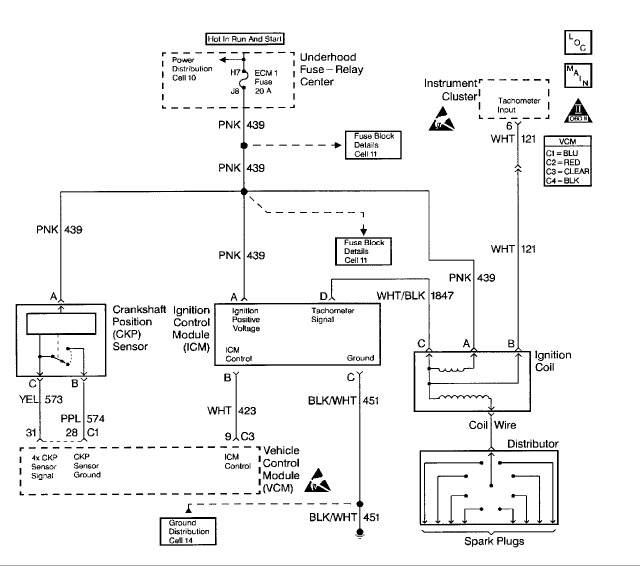
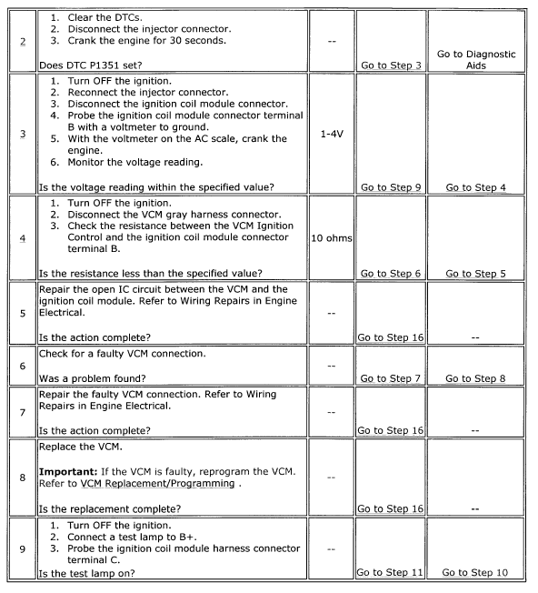
Here is the flow chart for that code

Circuit Description
The enhanced ignition system uses the crank sensor in order to provide the timing input to the VCM. The VCM uses this reference pulse in order to determine the individual ignition spark timing for each cylinder.
Once the VCM calculates the ignition timing, the ignition coil module on the IC circuit receives the timing signal. Each timing pulse received by the ignition coil module on the IC circuit triggers the coil module in order to operate the ignition coil. The secondary ignition voltage is induced, and then the secondary ignition voltage is sent to the distributor for distribution to each spark plug. This DTC is a type A DTC.
The IC signal voltage ranges from about 0.5 volt to 4.5 volts.
Conditions for Setting the DTC
EST enabled, and the engine speed is less than 250 RPM.
Action Taken When the DTC Sets
- The VCM turns the MIL ON when this DTC is reported and one failure has occurred.
- The VCM records the operating conditions at the time the Diagnostic Fails. Freeze Frame and Failure Records store this information.
Conditions for Clearing the MIL/DTC
The VCM turns OFF the MIL after 3 consecutive driving trips without a fault condition present. A history DTC will clear if no fault conditions have been detected for 40 warm-up cycles (the coolant temperature has risen 22°C (40°F) from the start-up coolant temperature and the engine coolant temperature exceeds 71°C (160°F) during that same ignition cycle) or the scan tool clearing feature has been used.
Diagnostic Aids
A poor connection, a rubbed through wire in the insulation, or a wire broken inside the insulation will cause an intermittent.
Check for the following conditions:
- Poor connection.
- Damaged harness; Inspect the VCM harness connectors for the following conditions:
- Backed out terminal C3 pin 9.
- Improper mating.
- Broken locks.
- Improperly formed or damaged terminals.
- A poor terminal to wire connection.
- Damage to the harness.
- Intermittent test - If the connections and the harness check OK, monitor a digital voltmeter connected between VCM connector C3 pin 9 and C4 pin 18 while moving related connectors and wiring harness. If the failure is induced, the voltage reading will change. This may help to isolate the location of the malfunction.
Test Description
The numbers below refer to the step numbers in the diagnostic table.
- This determines if the DTC is an intermittent.
- This check determines if the IC signal from the VCM is available at the ignition coil driver.
- The remaining tests begin to check that the coil driver circuitry is OK.


~~~~~~~~~~~~~~~~~~~~~~~~~~~~~~~~~~~~~~~~~~~~~~~~~~~~~~~~~~~~~~~~~~~~
We offer help in answering questions, clarifying things or giving advice but we are not a substitute for an on-site inspection by a professional.
|
|
|  |

|

slingsteel
New User
Jul 5, 2014, 2:35 PM
Post #3 of 10
(7170 views)
|
Thanks for the quick response Hammer Time
A couple of questions, in the diagnostic chart which column is the Yes and No?
Second question when it says disconnect injector connector, is that the one on top of the spider.
Also it Refers to Wiring Repair in the engine electrical?
Were can I find this, on the Internet or do I need a specific manual?
Thanks
|
|
|  |

|

nickwarner
Veteran
/ Moderator

Jul 5, 2014, 2:40 PM
Post #4 of 10
(7165 views)
|
He got that info from Alldata. He has the pro version but you can go to alldatadiy.com and for about $26 a year you can get the same thin for your truck. As you can see, its very helpful and since you know enough about how to work on this and know how to work a scope the tech information will be something you can understand.
|
|
|  |

|

Hammer Time
Ultimate Carjunky
/ Moderator

Jul 5, 2014, 2:43 PM
Post #5 of 10
(7165 views)
|
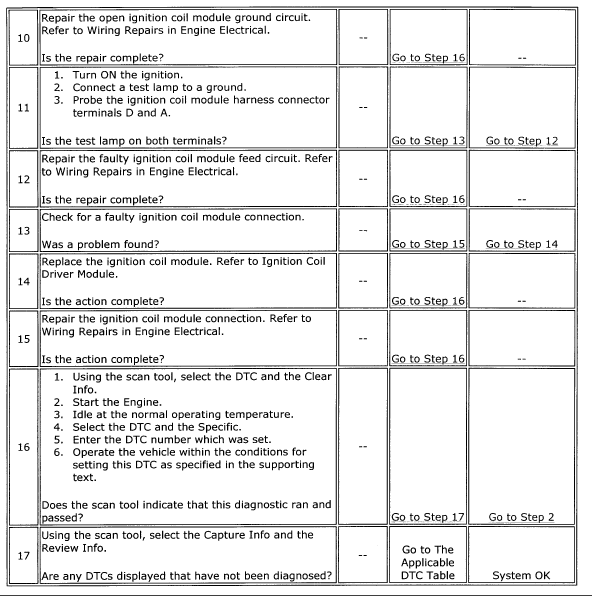
Here's the image I skipped.

Yes, they are referring to the main injector connector'
The wiring repair referral is just telling you to look at instructions on how to repair a wire. Solder and heat shrink is what they recommend.
~~~~~~~~~~~~~~~~~~~~~~~~~~~~~~~~~~~~~~~~~~~~~~~~~~~~~~~~~~~~~~~~~~~~
We offer help in answering questions, clarifying things or giving advice but we are not a substitute for an on-site inspection by a professional.
|
|
|  |

|

Discretesignals
Ultimate Carjunky
/ Moderator

Jul 6, 2014, 3:16 AM
Post #6 of 10
(7155 views)
|
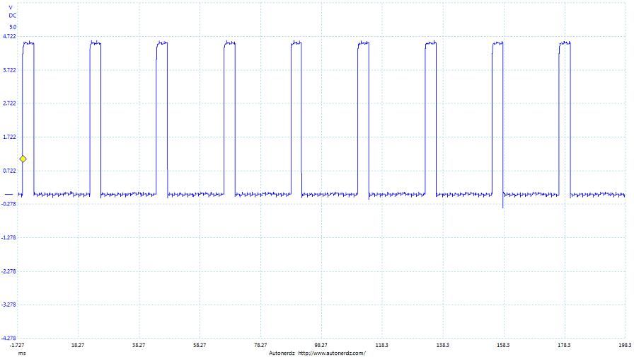
I've run into that code a few times on those. Usually it requires checking the voltage on the IC trigger circuit. A scope would be best for checking that circuit, but you might be able to get away with using a volt meter. Inspect the connector and wiring at the ignition control module really good. Sometimes you'll get a broken wire inside the insulation at the connector. The white wire is the IC trigger wire. Usually if you have an open or short, the engine won't run. If it is the module causing that, replace it with an AC Delco brand.
Here is what the signal should look like with the engine idling or cranking:

Since we volunteer our time and knowledge, we ask for you to please follow up when a problem is resolved.
(This post was edited by Discretesignals on Jul 6, 2014, 3:19 AM)
|
|
|  |

|

kev2
Veteran

Jul 6, 2014, 4:20 AM
Post #7 of 10
(7145 views)
|
I did not want to comment BUT
As discretesignals (DS) alludes to this is a quirky code- it will have A Tech chasing all avenues...as he mentions using the heavy artillery - lab scope - PCM pin outs- the trouble tree by HAMMERTIME points you right at the suspect terminal B -
and the trouble tree steps 2 and 3 will get this trouble shoot started...
I would start by CLEARING the code- check the notes then follow tree
NOTES- this code will set if - engine does not stasrt right up - lots of cranking will set it- interference on wire- leakiing secondary-
|
|
|  |

|

slingsteel
New User
Jul 6, 2014, 5:33 AM
Post #8 of 10
(7138 views)
|
Thanks everybody for all the responses.
I will try and get back to it as soon as the rain quits.
I live in Fl. and its raining cats and dogs right now.
Truck is sitting outside, not in the garage so its a pain in the ass to get anything done with this weather.
|
|
|  |

|

kev2
Veteran

Jul 6, 2014, 6:50 AM
Post #9 of 10
(7132 views)
|
i Am looking for my personal notes - FYI if a ICM is the issue be advised they can test GOOD even with a problem.Only use a GM OEM - autozone warranties replaces their ICM on a regular basis GM does not have to. wonder why?
|
|
|  |

|

slingsteel
New User
Jul 13, 2014, 9:36 AM
Post #10 of 10
(7099 views)
|
I finally got to do a little work on the truck.
When I left off truck was not running, just turn over then stumble when key was released.
Yesterday Saturday I went out check codes, it had 2 codes now P1351 & P1361. I cleared them and tried to start truck to see if they would return. Truck started right up a little grayish smoke from the exhaust but cleared up and was running fine. Drove it around the yard and let it idle for about half hour.
No CEL ON ,stop and restarted the engine 10 times each time fine.
So to day I went to see if it would start,back to the no start condition CEL ON with P1351.
So I started with the diagnosis chart, step 3 .4 measure between 1-4V my reads greater than 4Vac.( reads 6.8Vac)
Step 4 says to disconnect VCM gray harness.(check resistance between VCM and ICM)
My VCM has 5 connectors they are labeled
BLACK,WHITE,RED,BLUE the 5th one is not labeled
but looks like power only 2 wires going into it.
The BLACK and WHITE are on top(top row) RED and BLUE are on the bottom or (bottom row.)
Maybe I am not looking at the VCM, the device I am describing is mounted above inner fender well on the drivers side.
I figured I would just ohm out all the connections in the diagram. Just not sure about VCM connections its only showing 3 pins: 9 C3, 28,C1 and 31 are these all coming from the gray connector I cannot find?
Thanks again
|
|
|  |

| |  |
|


